Radiographic Cephalometry

The literal meaning of cephalometry is head measurement, and such measurements can be taken both clinically and radiographically. The term radiographic cephalometry is used to describe head measurements taken from an X-ray image. Traditionally, radiographic cephalometry has been performed on standardized two-dimensional X-ray images called cephalograms. In this chapter, however, the authors discuss three-dimensional (3D) radiographic cephalometry, a relatively new methodology that aims to quantify facial form by using 3D data derived from computed tomography (CT).
Basic Principles of 3D Cephalometry
Cephalometry requires knowledge in 3 fields: biology, geometry, and statistics. In this section, the authors review the geometric principles of 3D cephalometry. Although some of the geometry is challenging, one should make an effort to learn it, as it is invaluable.
In orthognathic surgery, clinicians use cephalometry to determine the configuration of the jaws. Like other objects, jaws have four basic geometric properties: size, position, orientation, and shape. In addition, they have a fifth property: reflection symmetry. In the following sections, the authors describe how to measure each of these parameters in 3D.
Size Measurements
Size is an intrinsic property of an object, and is independent of the space it occupies. One can measure size using linear measurements (e.g., length, width, and height), areas, or volumes. In 3D cephalometry, the simplest size measurements are length, width, and height; they are calculated as the distance between 2 points (landmarks) located in 3D space. For example, one can measure the width of the maxilla by calculating the distance between palatal cusps of the first molars.
Position Measurements
Position refers to point location in space. With 3D cephalometry, one is interested in determining the location of the jaws. Yet the jaws are complex three-dimensional objects composed by thousands of points, each one with a different position; therefore, to determine jaw location, one is tasked with selecting a single point to represent the entire jaw. However, because there is no perfect point, in practice one must use several. In the maxilla, clinicians use the anterior nasal spine (ANS), point A, and upper incisal midpoint. The anterior nasal spine represents the basal bone of the maxilla, point A represents the apical base, and the upper incisal midpoint represents the dentition. In the mandible, clinicians use pogonion, point B, and the lower incisal midpoint. Pogonion represents the basal mandible, point B the apical base, and the lower incisal midpoint, the dentition.
Measuring position in one, two, and three dimensions requires one, two, and three numbers, respectively. Thus, any system that measures jaw position in 3D must utilize three numbers. In general, one can measure 3D position using one of three systems: Cartesian, cylindrical, and spherical. Cartesian systems use three distances. Cylindrical systems use two distances and one angle. Spherical systems use one distance and two angles. Because spherical systems are not used in cephalometry, they will not be described here.
A 3D Cartesian-coordinate-system consists of three perpendicular axes (number lines) that cross one another at zero. The transverse axis is x, the anteroposterior axis is y, and the vertical axis is z. Each pair of axes forms a reference plane. In this system, one locates any point by measuring the distances from that point to each reference plane. Location is expressed using 3 coordinates (x, y, z).
Using a Cartesian system in 3D cephalometry is straightforward. The anteroposterior, vertical, and transverse positions of any landmark are expressed as (x, y, z) coordinates in a standard anatomical reference system. Relative position between two landmarks is easily calculated using arithmetic. For example, if the anteroposterior coordinate of point A is 62, and the anteroposterior coordinate of nasion is 60. Point A is said to be 2 mm in front of Nasion (62-60=2).
A cylindrical system is an extension of the two-dimensional polar system; it is, therefore, easier to learn a cylindrical system by first learning the polar system. A polar system resides on a plane consisting of a fixed point—the pole—and a ray—the polar axis. From the pole, the polar axis points in a fixed direction. In this system, one determines the position of any point by first drawing a line segment from the point one is locating to the pole; this line segment is called the radius. One then measures the length of the radius (r), and the angle between the radius and the polar axis (θ). The position is expressed using two coordinates (r, θ) (Figure 12).
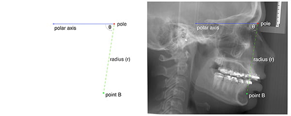
Figure 12
A cylindrical system adds one axis to the polar system. This axis, called the cylindrical axis, is perpendicular to the plane of the polar system and passes through the pole. In a cylindrical system, one measures the location of any point in 3D space by first projecting the point on the plane of the polar system. On this plane, one then establishes the position of the point projection using standard 2D polar coordinates (r, θ). The third coordinate is the distance from the point one is locating to the plane of the polar system.
Figure 13 illustrates how cylindrical systems work. In this example, the point B position is being measured in relation to sella-nasion (the anterior cranial base). The origin of the coordinate system (the pole) is nasion. The polar axis is the ray that originates on nasion, pointing at sella. The cylindrical axis is perpendicular to the median plane, crossing nasion. One establishes the location of point B by first projecting this point on the median plane, then by measuring r and θ on the plane. The radius (r) is the distance from the point-B-projection to nasion. Theta (θ) is the familiar SNB—the angle between sella-nasion (SN) and the point-B-projection. The last coordinate (transverse position) is the positive or negative distance between point B and the median plane.
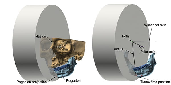
Figure 13
Orientation Measurements
Orientation is defined as the imaginary rotations required to move an object from a reference alignment to its current position. Let us clarify with an example. Figure 14 shows an airplane taking-off. Independent of its position or orientation in space, the airplane has a top, a bottom, a front, a back, a right side, and a left side. These intrinsic features can be used to draw three perpendicular axes: anteroposterior, top-bottom, and right-left (shown in the figure in light colors); combined, they form the airplane’s object coordinate system. As the term implies, object coordinate systems belong to objects. They are determined by the configuration of objects and, as such, they translate and rotate with them.
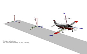
Figure 14
To continue, the space around the airplane also has a frame of reference. Like the airplane’s frame of reference, it also has three axes. In aeronautics, the axes of space are up-down, east-west, and north-south; combined, they make the world coordinate system. Figure 14 shows the world coordinate system at the beginning of the runway, in darker colors.
Gauging orientation, like measuring position, is always relative. To calculate it, one must decide on a reference orientation. For example, in this scenario the airplane’s orientation is being assessed in relation to the world. To measure orientation, one superimposes the origin of the object coordinate system (the airplane’s) onto the origin of the reference coordinate system (the world’s). Once this position has been established, pitch, roll, and yaw are measured.
Similarly, to measure jaw orientation, one compares the orientation of each jaw with the orientation of the whole head. For this, a computer program automatically constructs coordinate systems for each jaw (using a principal component analysis) and compares them with the coordinate system of the entire head (Figure 15). The order in which the software measures pitch, roll, and yaw is essential; these angles are not commutative. This means that the order in which they are measured affects the values derived. The authors recommend measuring yaw, roll, and then pitch, as employing this order is clinically relevant.
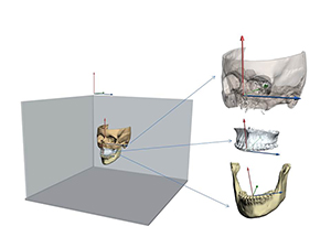
Figure 15
Shape Measurements
Shape is the geometric property of an object that is not size, not position, and not orientation.5, 23 As one can see, shape is defined by what it is not, rather than by what it is. When comparing two objects, shape is the characteristic that remains after objects have been scaled to the same size, placed at the same position, and rotated to the best possible alignment.
Figure 16 illustrates this concept. The figure depicts two mandibles: the top one (orange) is the average mandible; the lower one (blue) is deformed. These mandibles differ in size, position, orientation, and shape. To appreciate the differences in shape, it is necessary to first scale both mandibles to the same size. Next, one must place both mandibles in the same position. Finally, the deformed mandible is rotated until it is best aligned with the average mandible—the target. This process is known as Procrustes superimposition.5
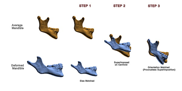
Figure 16
As one can see in the example: after the differences in size, position, and orientation have been removed, the deformed mandible has a distorted shape. Specifically, it has an obtuse gonial angle, and a relatively shorter ramus.
Symmetry Measurements
As mentioned previously, there are two factors related to symmetry. One is object symmetry, the other symmetric alignment. Object symmetry can be measured using a Procrustes Analysis,5, 23-27 a mathematical method that detects shape differences among similar objects. The analysis begins by superimposing objects optimally. For superimposition, the objects are first translated to the same location. Next, they are scaled to the same size. Then, one of them is kept static as a target, while the other is rotated until the distances between corresponding landmarks located in both objects become minimal.
At times, rather than looking for differences in shape, one is interested in comparing forms—form being the combination of size and shape. To compare forms, a Procrustes superimposition does not scale the objects to the same size. This is the type of Procrustes superimposition one uses to assess symmetry.
A Procrustes Analysis of Symmetry begins by dividing the form of a facial unit (e.g., the mandible) into two half-forms: right and left. To divide the form, the landmarks of the whole form are divided into 2 groups. The right set contains the coordinates of all the right landmarks, as well as all the midline landmarks; the left set contains the coordinates of all the left landmarks and the midline landmarks (Figure 17A and B). We then use each group of landmarks to create 2 half-forms.5, 23, 27
Next, using a series of transformations, we superimpose the 2 half-forms. However, before starting, we must pick one half-form to be the object of the transformations, with the other as the target. Which half-form (right or left) becomes the target is inconsequential.
The first transformation reflects (flips) one of the half-forms around its sagittal plane, creating a mirror image (Figure 17C). This operation makes the half-forms comparable. The second transformation centers both half-forms on a Cartesian coordinate system. To center the half-forms, we first determine the centroid of each. Then, we translate both forms, so that their centroids are on the origin (coordinates [0,0]) of the Cartesian system. The third transformation rotates the object half-form around its centroid until the form is aligned to the target. Alignment is reached when sum of all the distances between corresponding landmarks of the right and the left half-forms is minimal (Figure 17D).
To quantify the degree of asymmetry of each landmark, we measure the (partial) Procrustes distances between analogous right and left landmarks. These distances are directly proportional to the degree of asymmetry. Thus, they work well for our estimations.
Unfortunately, Procrustes superimposition is susceptible to the Pinocchio effect5, a phenomenon that occurs when outlier landmarks sway the alignment of a form, magnifying the Procrustes distances of other, less displaced, landmarks. Fortunately, we can curtail the Pinocchio effect generated by the most displaced landmarks by decreasing their weight on successive Procrustes superimpositions.
Figure 18 shows an example of using a Weighted Procrustes Analysis of Symmetry to measure the asymmetry of a mandible.
After calculating object symmetry, one measures symmetric alignment by calculating the movements (transformations) necessary to align the jaws to the median plane of the face. Here, three transformations are needed. They are transverse translation, roll, and yaw. Transverse translation places the incisal midpoint on the median plane. Roll rotates the jaws around the incisal midpoint until the right and left landmarks are vertically aligned. Yaw rotates the jaws around the incisal midpoint, minimizing distance differences between corresponding bilateral landmarks and the vertical reference planes—coronal and median. Ideal values for transverse position, yaw, and roll are zero.
Gateno-Xia 3D Cephalometric Analysis
The 3D cephalometric analysis of the authors is a grid (Table 2).7, 25 In each row, one assesses a different geometric property. Five properties are assessed: object symmetry, shape, size, position, orientation, and symmetric alignment. The columns belong to the individual facial units (e.g., maxilla and mandible).
In the first part of the analysis, object symmetry, one determines the intrinsic symmetry of each jaw. In the second part, shape, one measures the shape of the jaws using a 3D Procrustes analysis. In the third part, size, one measures the dimensions of each jaw: length, width, and height. In the fourth part of the analysis, position, one measures the location of the jaws on each facial axis—anteroposterior, vertical, and transverse. Depending on the preference of the clinician, position can be measured using a 3D Cartesian system or a cylindrical system. In the fifth and final part of the study, orientation, one measures the orientation of the jaws (i.e., yaw, roll, and pitch). Symmetric alignment is a composite of three measurements: transverse position, yaw, and roll.
Table of Contents
