Evaluation Of Patients With Jaw Deformities

- A primary diagnosis
- Secondary diagnoses and comorbidities, if present
- A statement detailing the severity of the deformity
- A list of impairments caused by the deformity
During the evaluation, the provider should collect all data necessary to undertake and complete the assessment process.
History
The history is obtained by interviewing the patient and is, therefore, the subjective component of the evaluation. It has multiple parts, including:
- Chief complaint(s)
- History of the present illness
- Past medical history
- Review of systems
The chief complaint describes the patient’s symptoms or problems. It should not be a statement of treatment (e.g., “I need surgery”). Examples of suitable chief complaints are: “I have difficulty chewing,” “my bite is off,” and/or “my face is crooked.”
The history of the present illness should comprehend the following:
- When did the deformity first become apparent and how did it evolve?
- Does the patient have chewing problems? In trying to ascertain this, one should be specific when questioning patients. Many tend to answer “no” to the general question: Do you have chewing problems? Yet they may answer in the positive when asked a more explicit question like: Can you cut food with your front teeth (i.e., incising)?
- Does the patient have breathing problems (e.g., mouth-breathing, snoring, or witnessed apnea)?
- Does the patient have speech problems?
- Does the patient have social or emotional problems related to the deformity?
- Does the patient have other comorbid conditions? One should ask about TMJ symptoms (e.g., joint pain, joint noises, limited or abnormal motion), soft-tissue impingements, and/or other diseases that may affect the jaws.
Physical Examination
In this section, the authors present a problem-focused physical examination aimed at evaluating jaw deformities. The examination is divided into two parts: an assessment of facial form and a cursory evaluation. The purpose of the first is to determine the presence, extent, and severity of a deformity; the second seeks to identify signs of disease. The assessment of facial form includes evaluations of facial soft-tissue and dentition. The goal is to diagnose a jaw deformity; however, as the skeleton cannot be inspected, one infers bone deformity by appraising facial appearance and dentition.
During the physical examination, the examiner must determine the size, position, orientation, shape, and symmetry of the jaws. Assessing three of these properties—position, orientation, and symmetry—requires a frame of reference, the most useful of which is that defined by the standard anatomical planes: median, coronal, and axial.6, 7, 10 The median plane (i.e., the plane of symmetry of the face) divides the face into right and left halves; the coronal plane divides the face into anterior and posterior portions; and the axial plane divides the face into upper and lower segments. These planes are mutually perpendicular, or orthogonal. The lines of intersection between the planes form the axes of the face. The intersection of the medial and axial planes forms the anteroposterior axis, the intersection of the medial and coronal planes forms the vertical axis, and the intersection of the axial and coronal planes forms the transverse axis. These axes define the cardinal directions of the face: front, back, cranial, caudal, right, and left (Figure 3).
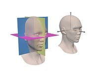
Figure 3
Throughout the physical examination, the planes of our reference system (i.e., median, axial, and coronal) are imaginary. We mentally construct them, while observing the patient in a standard reference posture.
The standard reference posture of the head is the natural head posture (NHP).10-12 The NHP is a component of standard international anatomical alignment, a reference position in which a subject is standing erect, feet together, and hands to the side, with the face looking forward toward the horizon. In this posture the head is not flexed or extended, nor is it rotated or tilted.
Clinical Assessment of Jaw Position
During the physical examination, one determines the position of the maxilla and mandible in three-dimensional space. This is done separately for each facial axis: anteroposterior, vertical, and transverse.
Anteroposterior
One infers the anteroposterior position of the jaws by evaluating the anteroposterior occlusal relationships and the facial profile. The occlusal relationships are appraised at three different sites: first molar, canine, and central incisor (Figure 3). With this appraisal, the frame of reference is the upper dentition and the examiner gauges the anteroposterior position of the lower teeth in relation to a hypothetical static upper.
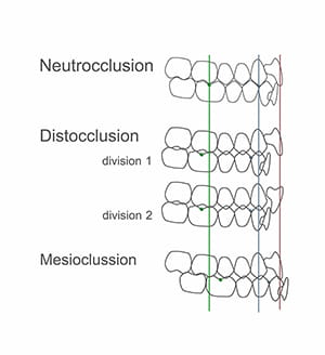
Figure 4
Angle’s classifications of molar relationship assesses the position of the buccal groove of the lower first molar in relation to the mesiobuccal cusp of the upper.13 In an ideal Class I molar relationship, these landmarks coincide (i.e., align). In a Class II relationship, the lower molar groove is behind the upper cusp; whereas, in a Class III, it is in front. The canine region is assessed in a similar manner. In a Class I canine relationship, the lower-canine-first-premolar embrasure coincides with the cusp of the upper canine. In a Class II, the embrasure is behind the upper canine cusp; with a Class III, it is in front.
Finally, for the incisal region, we measure the overjet, which is defined as the horizontal distance between the incisal edges of the upper and lower central incisors. When the lower incisal edge coincides with the upper, the overjet is zero. When it is behind, the measurement has a positive value; when in front, it will be negative. The ideal overjet is +2mm.
Based on the above referenced assessments, one classifies the occlusion into neutrocclusion, distocclusion, or mesiocclusion. In neutrocclusion, the molar and canine relationships are Class I and the overjet is normal. In distocclusion, the molar and canine relationships are Class II and the overjet is either greater than normal (Division 1) or normal (Division 2). In mesiocclusion, the molar and canine relationships are Class III and the overjet is smaller than normal, usually negative.
Distocclusion can occur in many different configurations:
- Backward-positioned mandible with a normally positioned maxilla
- Backward mandible with a forward maxilla
- Backward mandible with a less backward maxilla
- Normal mandible with forward maxilla
- Forward mandible with more forward maxilla
Thus, the finding of mesiocclusion or distocclusion reveals a discrepancy in jaw position between the upper and lower jaws, and cannot be used independently to determine anteroposterior jaw position. Also note that the finding of neutrocclusion does not necessarily imply normal anteroposterior jaw position, as both jaws can be retrognathic or prognathic.
To complete the assessment of anteroposterior jaw position, one also evaluates the facial profile.13-16 Traditionally, clinicians have assessed the profile by classifying it into one of three categories: straight, convex, or concave. However, this assessment lacks specificity. For example, a concave profile can occur when the upper jaw is normal and the lower jaw is prognathic, when the upper jaw is retrognathic and the lower jaw is normal, or when the upper jaw is retrognathic and the lower jaw is prognathic.
A better method is to compare the anteroposterior position of each jaw with the anterior boundary of the cranial base. Three structures related to the anterior cranial base—soft-tissue glabella, soft-tissue nasion, and the most anterior aspect of the cornea—have been successfully employed to define the anteroposterior position of a coronal plane of reference.
When assessing the facial profile, the patient should be in standard anatomical alignment (i.e., head in the NHP), with the clinician observing from the side. While in this position, the clinician imagines a coronal plane of reference—a plane that can be tangential to soft-tissue glabella, soft-tissue nasion, or the anterior surface of the cornea. Concurrently, the clinician infers the anteroposterior position of the jaws by assessing the position of the lips and chin in relation to this paracoronal plane (Figure 5).
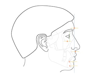
Figure 5
No perfect reference plane exists for determining the anteroposterior position of the jaws. Nasion can be obscured in Asian patients, as it is commonly located posterior to the cornea; glabella can be distorted in frontal bossing; and distances from the cornea are difficult to gauge clinically. Notwithstanding these limitations, our clinical impressions are reliable because our brains have the innate ability to discern the correct anteroposterior position.
Vertical
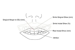
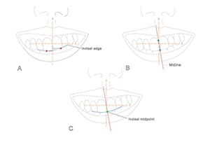
Clinically, one determines the vertical position of the maxilla by measuring the rest-incisal-show and the smile-dento-gingival-show (Figure 6). Rest-incisal-show is the amount of upper incisor that is exposed when the lips are relaxed. It is the vertical distance from the upper lip stomion to the maxillary incisal midpoint. Stomion is the midpoint of the free-edge of a lip, upper or lower. The incisal midpoint is the point at the intersection of the dental midline and the arc defined by the incisal edges (Figure 7). It represents the middle of the dental arch. When the maxillary incisal midpoint is below stomion (baseline), the rest-incisal-show is positive; when above, it is negative. Rest-incisal-show should be measured at the incisal midpoint rather than at other points on the incisal edges because, when the maxilla is canted, incisal show varies at each location (Figure 7).
Rest-incisal-show should be measured on an upright patient, as it can increase when the patient is supine (Figure 8). Additionally, the eyes of the examiner should be level with the patient’s lips, as looking from above hides the teeth, and viewing from below exposes them. Negative incisal shows are difficult to measure. To overcome this challenge, the authors place a piece of wax on the lingual surfaces of the upper incisors, extending it downward below the lip. Subsequently, the clinician asks the patient to relax his lips and marks (on the wax) the position of the upper lip stomion. Finally, the clinician pulls the upper lip up and, with a caliper, measures the distance from the mark to the incisal midpoint (Figure 9). Some patients may have incisal attrition, which is the erosion of the incisal edges due to grinding. In this situation, the examiner should add the amount of tissue loss to the measurement.
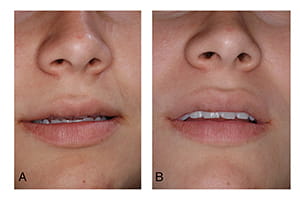
Figure 8
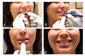
Figure 9
To determine the vertical position of the maxilla, the examiner compares the patient’s rest-incisal-show with normal values. Gender, age, ethnicity, and the length of the upper lip influence these values.17 Female patients have more incisal show than males. Incisal show also decreases with age.17, 18 Caucasians tend to have more incisal show than patients of other ethnicities.17 Patients with short upper lips tend to have more incisal show than those with longer lips.17 For example, a five-millimeter incisal show is considered normal in a teenage girl with a short upper lip, while a one-half millimeter incisal show is considered normal in a 60-year-old male. Patients with a negative incisal show are deemed to have deficient maxillary downward displacement, and patients with incisal shows above the normal range for their particular gender, age, ethnicity, and length of upper lip are deemed to have excessive maxillary downward displacement.
As stated previously, smile-dento-gingival-show is also used to determine the vertical position of the maxilla. Smile-dento-gingival-show is the amount of central incisor and labial gingiva displayed when smiling. Tooth show is measured as a percent of its height, while gingival show is measured in millimeters. While smiling, most patients with normal vertical maxillary position display 100% of their incisors19 and up to 2 mm of gum. Patients with superiorly positioned maxillae show less than 100% of their incisors, whereas patients with inferiorly positioned maxillae display an excessive amount of gum.20 Yet the amount of tooth and gum displayed during the process of smiling is not only related to the vertical position of the maxilla, it is also associated with lip animation and passive dental eruption.
Too much or too little tooth and gum displayed during smiling may be a consequence of abnormal lip animation.21, 22 A hyperactive smile—caused by hyperactive smile muscles—produces a “gummy” smile; a hypoactive or weak smile, results in significantly less tooth display. Hyperactive smile is diagnosed when the gingival-show is large, the rest-incisal-show is normal, and passive dental eruption (next paragraph) is normal. A hypoactive smile is diagnosed when the smile-tooth-display is small and the rest-incisal-show is normal.
Tooth eruption can consist of active and passive phases. Active eruption is the movement of teeth toward the occlusal plane, while passive eruption is related to the exposure of teeth through apical migration of the gingiva. When passive eruption does not progress, the result is a dental crown that appears short because of the presence of excess gingiva covering the enamel. Clinically, the most obvious sign of delayed passive eruption is a short clinical crown; also, sulcus depths, from the gingival margin to the cement-enamel-junction, are large (over 3 mm).1
Patients with delayed passive eruption may have large smile-gingival-shows, despite normal vertical maxillary position. In this scenario, the smile-gingival-show is large, but the rest-incisal-show is small or normal.
Transverse
Clinically, transverse jaw position is established by measuring the distance between middle landmarks and the median plane. In the maxilla, one solely measures the position of the upper incisal midpoint. In the mandible, however, one measures the position of two points: the lower incisal midpoint and soft-tissue pogonion (i.e., the most prominent point of the soft-tissue chin). The transverse position should be measured at the incisal midpoint points rather than any other point on the dental midline because when the jaws are canted, measurements vary with point position (Figure 7). Also, when assessing the transverse position of the mandible, the mandible must be in centric relationship—the mandibular position in which the condyles are fully seated within the glenoid fossae.
Clinical Assessment of Jaw Orientation
During the physical examination, the pitch, roll, and yaw of the jaws is assessed in relation to the frame of reference of the entire face—the system defined by the median, axial, and coronal planes.7 Pitch is difficult to measure clinically and is best assessed with radiographic cephalometry. Roll and yaw are related to symmetry and are discussed in the following section.
Clinical Assessment of Jaw Symmetry
The plane of symmetry of the face is the median plane. Midline landmarks like glabella, nasion, subnasale, incisal midpoint, and pogonion should lie on the median plane. Bilateral structures like the eyes, ears, and gonial angles should be aligned on each side of the median plane, as mirror images.
During the physical examination, one infers the symmetry of the jaws by inspecting the face and examining the dentition. To assess facial symmetry, the examiner must first stand in front of the patient, looking at his/her face. While doing this, he should mentally visualize the median plane and appraise two factors. First, it must be determined if the midline structures are on the median plane; second, one must establish whether bilateral structures are positioned as mirror images in relation to this plane. The examiner should also inspect the face from above and below to ascertain if bilateral structures have the same anteroposterior position. All deviations should be measured and recorded (Figure 10).
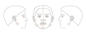
Figure 10
Clinicians also determine symmetric jaw alignment by examining the dentition. When the jaws are symmetrically aligned, the upper and lower incisal midpoints lie on the median facial plane. Also, corresponding right and left teeth have the same vertical position and the same horizontal distance to the median and coronal planes.
Transverse deviations of the upper and lower incisal midpoints should be measured and recorded. The roll of the maxilla can be clinically determined by measuring, with a Boley gauge, the vertical distances from each medial canthus to the ipsilateral maxillary teeth (Figure 11). Right-left differences that are consistent through the arch indicate canting (abnormal roll) of the upper jaw. These measurements should be interpreted with caution as they can be affected by local dental irregularities, vertical eye dystopia, and yaw malrotation of the upper jaw.
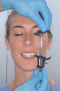
Figure 11
Diagnostic Test
Jaw deformities cannot be fully assessed clinically. Hence, there is a need to gather additional information derived from diagnostic tests that may include imaging studies, radiographic cephalometry, and/or dental model analyses.
Radiographic Cephalometry
The literal meaning of cephalometry is head measurement, and such measurements can be taken both clinically and radiographically. The term radiographic cephalometry is used to describe head measurements taken from an X-ray image. Traditionally, radiographic cephalometry has been performed on standardized two-dimensional X-ray images called cephalograms. In this chapter, however, the authors discuss three-dimensional (3D) radiographic cephalometry, a relatively new methodology that aims to quantify facial form by using 3D data derived from computed tomography (CT).
Basic Principles of 3D Cephalometry
Cephalometry requires knowledge in 3 fields: biology, geometry, and statistics. In this section, the authors review the geometric principles of 3D cephalometry. Although some of the geometry is challenging, one should make an effort to learn it, as it is invaluable.
In orthognathic surgery, clinicians use cephalometry to determine the configuration of the jaws. Like other objects, jaws have four basic geometric properties: size, position, orientation, and shape. In addition, they have a fifth property: reflection symmetry. In the following sections, the authors describe how to measure each of these parameters in 3D.
Size Measurements
Size is an intrinsic property of an object, and is independent of the space it occupies. One can measure size using linear measurements (e.g., length, width, and height), areas, or volumes. In 3D cephalometry, the simplest size measurements are length, width, and height; they are calculated as the distance between 2 points (landmarks) located in 3D space. For example, one can measure the width of the maxilla by calculating the distance between palatal cusps of the first molars.
Position Measurements
Position refers to point location in space. With 3D cephalometry, one is interested in determining the location of the jaws. Yet the jaws are complex three-dimensional objects composed by thousands of points, each one with a different position; therefore, to determine jaw location, one is tasked with selecting a single point to represent the entire jaw. However, because there is no perfect point, in practice one must use several. In the maxilla, clinicians use the anterior nasal spine (ANS), point A, and upper incisal midpoint. The anterior nasal spine represents the basal bone of the maxilla, point A represents the apical base, and the upper incisal midpoint represents the dentition. In the mandible, clinicians use pogonion, point B, and the lower incisal midpoint. Pogonion represents the basal mandible, point B the apical base, and the lower incisal midpoint, the dentition.
Measuring position in one, two, and three dimensions requires one, two, and three numbers, respectively. Thus, any system that measures jaw position in 3D must utilize three numbers. In general, one can measure 3D position using one of three systems: Cartesian, cylindrical, and spherical. Cartesian systems use three distances. Cylindrical systems use two distances and one angle. Spherical systems use one distance and two angles. Because spherical systems are not used in cephalometry, they will not be described here.
A 3D Cartesian-coordinate-system consists of three perpendicular axes (number lines) that cross one another at zero. The transverse axis is x, the anteroposterior axis is y, and the vertical axis is z. Each pair of axes forms a reference plane. In this system, one locates any point by measuring the distances from that point to each reference plane. Location is expressed using 3 coordinates (x, y, z).
Using a Cartesian system in 3D cephalometry is straightforward. The anteroposterior, vertical, and transverse positions of any landmark are expressed as (x, y, z) coordinates in a standard anatomical reference system. Relative position between two landmarks is easily calculated using arithmetic. For example, if the anteroposterior coordinate of point A is 62, and the anteroposterior coordinate of nasion is 60. Point A is said to be 2 mm in front of Nasion (62-60=2).
A cylindrical system is an extension of the two-dimensional polar system; it is, therefore, easier to learn a cylindrical system by first learning the polar system. A polar system resides on a plane consisting of a fixed point—the pole—and a ray—the polar axis. From the pole, the polar axis points in a fixed direction. In this system, one determines the position of any point by first drawing a line segment from the point one is locating to the pole; this line segment is called the radius. One then measures the length of the radius (r), and the angle between the radius and the polar axis (θ). The position is expressed using two coordinates (r, θ) (Figure 12).
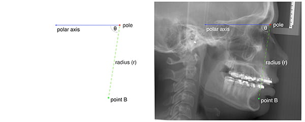
Figure 12
A cylindrical system adds one axis to the polar system. This axis, called the cylindrical axis, is perpendicular to the plane of the polar system and passes through the pole. In a cylindrical system, one measures the location of any point in 3D space by first projecting the point on the plane of the polar system. On this plane, one then establishes the position of the point projection using standard 2D polar coordinates (r, θ). The third coordinate is the distance from the point one is locating to the plane of the polar system.
Figure 13 illustrates how cylindrical systems work. In this example, the point B position is being measured in relation to sella-nasion (the anterior cranial base). The origin of the coordinate system (the pole) is nasion. The polar axis is the ray that originates on nasion, pointing at sella. The cylindrical axis is perpendicular to the median plane, crossing nasion. One establishes the location of point B by first projecting this point on the median plane, then by measuring r and θ on the plane. The radius (r) is the distance from the point-B-projection to nasion. Theta (θ) is the familiar SNB—the angle between sella-nasion (SN) and the point-B-projection. The last coordinate (transverse position) is the positive or negative distance between point B and the median plane.
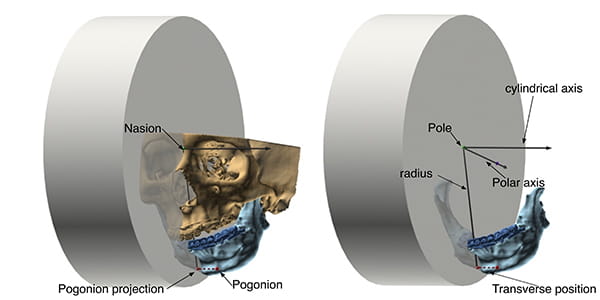
Figure 13
Orientation Measurements
Orientation is defined as the imaginary rotations required to move an object from a reference alignment to its current position. Let us clarify with an example. Figure 14 shows an airplane taking-off. Independent of its position or orientation in space, the airplane has a top, a bottom, a front, a back, a right side, and a left side. These intrinsic features can be used to draw three perpendicular axes: anteroposterior, top-bottom, and right-left (shown in the figure in light colors); combined, they form the airplane’s object coordinate system. As the term implies, object coordinate systems belong to objects. They are determined by the configuration of objects and, as such, they translate and rotate with them.
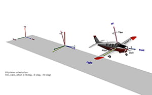
Figure 14
To continue, the space around the airplane also has a frame of reference. Like the airplane’s frame of reference, it also has three axes. In aeronautics, the axes of space are up-down, east-west, and north-south; combined, they make the world coordinate system. Figure 14 shows the world coordinate system at the beginning of the runway, in darker colors.
Gauging orientation, like measuring position, is always relative. To calculate it, one must decide on a reference orientation. For example, in this scenario the airplane’s orientation is being assessed in relation to the world. To measure orientation, one superimposes the origin of the object coordinate system (the airplane’s) onto the origin of the reference coordinate system (the world’s). Once this position has been established, pitch, roll, and yaw are measured.
Similarly, to measure jaw orientation, one compares the orientation of each jaw with the orientation of the whole head. For this, a computer program automatically constructs coordinate systems for each jaw (using a principal component analysis) and compares them with the coordinate system of the entire head (Figure 15). The order in which the software measures pitch, roll, and yaw is essential; these angles are not commutative. This means that the order in which they are measured affects the values derived. The authors recommend measuring yaw, roll, and then pitch, as employing this order is clinically relevant.
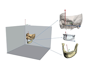
Figure 15
Shape Measurements
Shape is the geometric property of an object that is not size, not position, and not orientation.5, 23 As one can see, shape is defined by what it is not, rather than by what it is. When comparing two objects, shape is the characteristic that remains after objects have been scaled to the same size, placed at the same position, and rotated to the best possible alignment.
Figure 16 illustrates this concept. The figure depicts two mandibles: the top one (orange) is the average mandible; the lower one (blue) is deformed. These mandibles differ in size, position, orientation, and shape. To appreciate the differences in shape, it is necessary to first scale both mandibles to the same size. Next, one must place both mandibles in the same position. Finally, the deformed mandible is rotated until it is best aligned with the average mandible—the target. This process is known as Procrustes superimposition.5
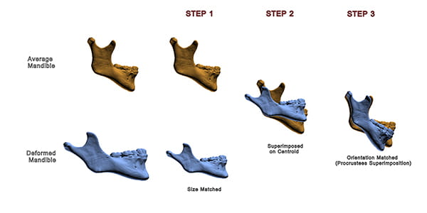
Figure 16
As one can see in the example: after the differences in size, position, and orientation have been removed, the deformed mandible has a distorted shape. Specifically, it has an obtuse gonial angle, and a relatively shorter ramus.
Symmetry Measurements
As mentioned previously, there are two factors related to symmetry. One is object symmetry, the other symmetric alignment. Object symmetry can be measured using a Procrustes Analysis,5, 23-27 a mathematical method that detects shape differences among similar objects. The analysis begins by superimposing objects optimally. For the superimposition, the objects are first translated to the same location. Next, they are scaled to the same size. Then, one of them is kept static as a target, while the other is rotated until the distances between corresponding landmarks located in both objects become minimal.
At times, rather than looking for differences in shape, one is interested in comparing forms—form being the combination of size and shape. To compare forms, a Procrustes superimposition does not scale the objects to the same size. This is the type of Procrustes superimposition one uses to assess symmetry.
A Procrustes Analysis of Symmetry begins by dividing the form of a facial unit (e.g., the mandible) into two half-forms: right and left (Figure 17A). To divide the form, the landmarks of the whole form are divided into 2 groups. The right set contains the coordinates of all the right landmarks as well as all the midline landmarks (Figure 17B); the left set contains the coordinates of all the left landmarks and the midline landmarks (Figure 17C). We then use each group of landmarks to create 2 half-forms.5, 23, 27
Next, using a series of transformations, we superimpose the 2 half-forms. However, before starting, we must pick one half-form to be the object of the transformations, with the other as the target. Which half-form (right or left) becomes the target is inconsequential.
The first transformation reflects (flips) one of the half-forms around its sagittal plane, creating a mirror image (Figure 17D). This operation makes the half-forms comparable. The second transformation centers both half-forms on a Cartesian coordinate system. To center the half-forms, we first determine the centroid of each. Then, we translate both forms, so that their centroids are on the origin [coordinates (0, 0)] of the Cartesian system. The third transformation rotates the object half-form around its centroid until the form is aligned to the target. Alignment is reached when sum of all the distances between corresponding landmarks of the right and the left half-forms is minimal (Figure 17E).
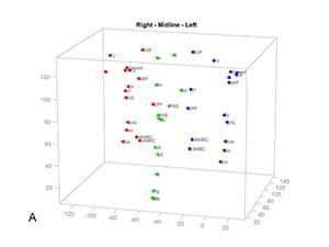
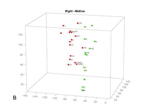
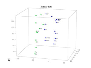
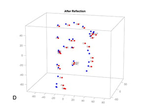
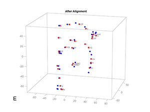
Figure 17. Procrustes Analysis of Symmetry. A) A mandible has three groups of landmarks, right, middle and left. The landmarks of the whole mandible are divided into 2 groups to create 2 half-forms: B) the right set contains the coordinates of all the right landmarks and all the midline landmarks; C) the left set contains the coordinates of all the left landmarks and the midline landmarks. D) The right set is reflected to the left, creating a mirror image. E) The reflected right set is iteratively aligned to the left set till the sum of all the distances between corresponding landmarks of the right and the left half-forms is minimal.
To quantify the degree of asymmetry of each landmark, we measure the (partial) Procrustes distances between analogous right and left landmarks. These distances are directly proportional to the degree of asymmetry. Thus, they work well for our estimations.
Unfortunately, Procrustes superimposition is susceptible to the Pinocchio effect5, a phenomenon that occurs when outlier landmarks sway the alignment of a form, magnifying the Procrustes distances of other, less displaced, landmarks. Fortunately, we can curtail the Pinocchio effect generated by the most displaced landmarks by decreasing their weight on successive Procrustes superimpositions.
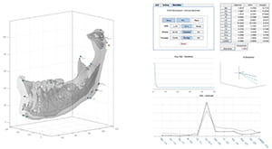
Figure 18
Figure 18 shows an example of using a Weighted Procrustes Analysis of Symmetry to measure the asymmetry of a mandible.
After calculating object symmetry, one measures symmetric alignment by calculating the movements (transformations) necessary to align the jaws to the median plane of the face. Here, three transformations are needed. They are transverse translation, roll, and yaw. Transverse translation places the incisal midpoint on the median plane. Roll rotates the jaws around the incisal midpoint until the right and left landmarks are vertically aligned. Yaw rotates the jaws around the incisal midpoint, minimizing distance differences between corresponding bilateral landmarks and the vertical reference planes—coronal and median. Ideal values for transverse position, yaw, and roll are zero.
Gateno-Xia 3D Cephalometric Analysis
The 3D cephalometric analysis of the authors is a grid (Table 2).7, 25 In each row, one assesses a different geometric property. Five properties are assessed: object symmetry, shape, size, position, orientation, and symmetric alignment. The columns belong to the individual facial units (e.g., maxilla and mandible).
In the first part of the analysis, object symmetry, one determines the intrinsic symmetry of each jaw. In the second part, shape, one measures the shape of the jaws using a 3D Procrustes analysis. In the third part, size, one measures the dimensions of each jaw: length, width, and height. In the fourth part of the analysis, position, one measures the location of the jaws on each facial axis—anteroposterior, vertical, and transverse. Depending on the preference of the clinician, position can be measured using a 3D Cartesian system or a cylindrical system. In the fifth and final part of the study, orientation, one measures the orientation of the jaws (i.e., yaw, roll, and pitch). Symmetric alignment is a composite of three measurements: transverse position, yaw, and roll.
Dental Model Analysis
A dental model analysis is an essential component in the evaluation of patients requiring orthognathic surgery. It is done at least twice: before orthodontics and prior to surgery. The first analysis—the initial dental model analysis—guides orthodontic treatment; the second—the progress dental model analysis—establishes readiness for surgery.
In orthognathic surgery, surgeons and orthodontists collaborate to normalize the jawbones and the occlusion. In the first stage of treatment, an orthodontist aligns the upper and lower teeth to their corresponding jaw, creating normal dental arches. A surgeon then aligns the arches with one other during surgery. The orthodontist’s task is complex. He/she must coordinate the dental arches so that they can be placed in normal intercuspation at surgery. Coordination of dental arches entails giving the dental arches (upper and lower) corresponding forms. An initial dental model analysis shows the clinician how the pretreatment form deviates from the target, which is essential to planning correction.
An initial dental model analysis includes the following:
- Analyses of shape
- Arch shape correspondence
- Dental alignment
- Dental leveling
- Curve of Spee
- Buccolingual inclinations
- Analyses of size
- Spacing
- Arch width
- Bolton assessment
A dental model analysis has multiple components, which the authors have classified into two groups: Appraisals of shape and appraisals of size. The first appraisal of shape is arch shape correspondence. For teeth to fit into a normal occlusion, the shapes of the upper and lower dental arches must be similar. This is called arch shape correspondence. To assess it, one looks at the occlusal surfaces of both models simultaneously, mentally comparing the shapes of both arches. Dissimilar shapes are a problem; for instance, a “U” shaped lower arch will not fit a “V” shaped upper arch, and a square lower arch will not fit a “U” shaped upper arch.
The second appraisal of shape, evaluates dental alignment. With perfect alignment, the edges of the incisors and the buccal-cusp-ridges of canines, premolars, and molars make a catenary arch. Misalignment occurs when the teeth are not aligned in an arch, because of malrotation, displacement, or tipping.
The third shape appraisal evaluates dental leveling. Leveling refers to the vertical position of teeth in relation to the occlusal plane. The occlusal surfaces of all teeth should be on the plane.
The fourth shape appraisal assesses the curve of Spee.28 The curve of Spee is the up-down curvature of the occlusal plane. It starts in the canine and extends back, to the last molar. An ideal curve of Spee is flat or has minimal upward concavity.29
The fifth and final shape assessment appraises the buccolingual inclination of posterior teeth. In the mandible, the lingual cusps should be 1 mm lower than the buccal. In the maxilla, the buccal cusps should be 1 mm higher than the palatal. Buccolingual inclination is assessed with a straightedge. In the mandible, the straightedge is placed on corresponding buccal cusps and the gap between the tool and the lingual cusps is measured. In the maxilla, the straightedge is placed on the palatal cusps and the gap between the instrument and the buccal cusps is measured.
The next group of measurements appraises size. Among them is spacing, which is a comparison between the space available for the alignment of teeth and the space required. In the first step, one calculates the available space: the arch perimeter from one first molar to the other. In the second step, an examiner measures the space needed, which is the sum of the widths of individual teeth—premolars, canines, and incisors.13
Another essential component of the size appraisal is arch width, which is measured at the first molars. In an ideal Class I occlusion, the mesiopalatal cusps of the upper first molars occlude with the distal fossae of the lower first molars. Thus, the distance between the mesiopalatal cusps of the maxillary first molars should be the same as the distance between the distal fossae of the mandibular first molars. A discrepancy between these measurements may reveal an underlying apical-base deformity.
Table of Contents
